

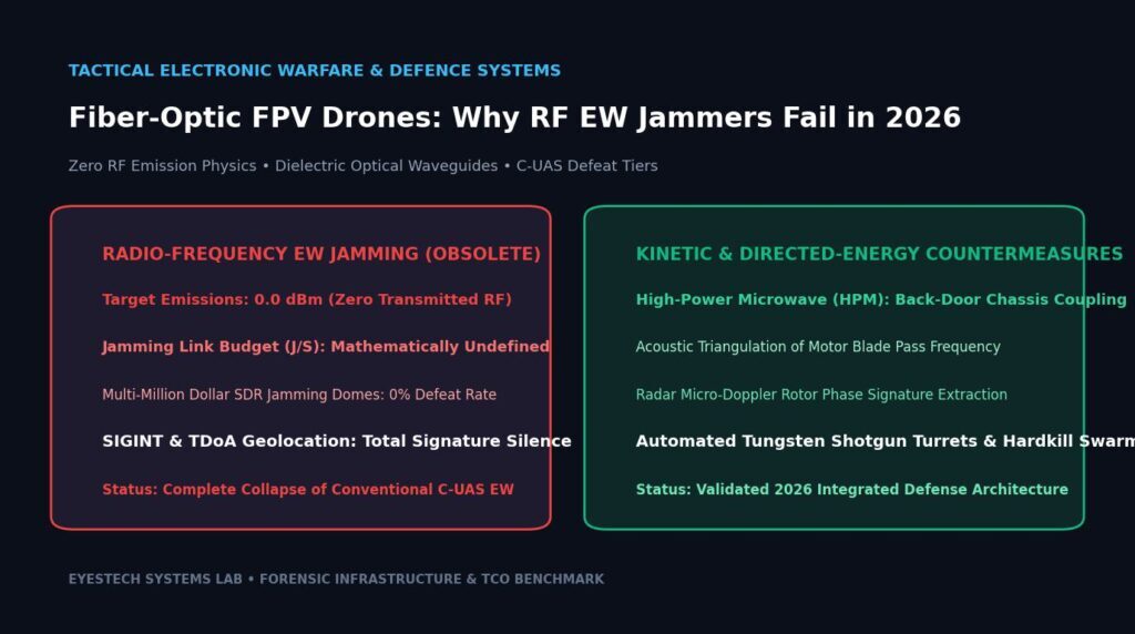

Fiber-optic FPV drones are difficult for radio-frequency jammers because their command and video link travels through a physical cable. That removes the radio link a jammer normally attacks, but it does not make the aircraft invulnerable. The spool adds mass, drag, range limits and a breakable route. Defenders must shift from spectrum denial to detection, physical interception, route protection and attacks on the launch or control chain.
Fiber-optic FPV drones expose a blind spot in counter-UAS thinking: a system can be excellent at denying radio control and still be ineffective against an aircraft whose critical link is glass. This article explains the engineering boundary clearly, separates public evidence from vendor claims, and gives operators a way to compare fiber-guided and radio-controlled systems without turning one battlefield adaptation into a universal performance promise.
- A fiber tether can bypass RF jamming of the command and video path.
- The aircraft remains vulnerable to physical damage, detection and onboard failures.
- Range, speed, video quality and survivability belong to a specific platform and test condition.
- The correct countermeasure is a layered sensor and interception problem, not a single replacement jammer.
Why the radio link disappears
A conventional FPV system normally exchanges at least two important streams over radio: control commands from the ground station and video from the aircraft. Electronic-support and jamming systems can search for those emissions, interfere with the receiver, or disrupt the navigation aids that help the aircraft hold a route. The exact bands and waveforms vary by platform, so a claim about “all FPVs” is already too broad.
A fiber-guided system moves the high-value exchange into a cable that pays out behind the aircraft. Electrical or optical interfaces at the two ends convert the operator’s commands and the camera feed into signals carried through the tether. A radio jammer can still flood the air around the drone, but that energy does not become a substitute for the missing radio path inside the glass.
That is the useful engineering statement: RF denial is aimed at a wireless path, while a fiber tether changes the path. Calling the drone “immune to electronic warfare” goes further than the evidence. Jamming is only one electronic attack. Electromagnetic interference can still affect onboard electronics, and a platform may use other radios, satellite-navigation receivers, telemetry links or data interfaces. A tether also creates non-electronic failure modes that a normal FPV does not have.
The J/S equation has a boundary
Traditional jammer analysis often expresses effectiveness through a jammer-to-signal ratio, or J/S, at the victim receiver. That model is useful when both the wanted signal and the interference arrive through the electromagnetic channel. It is the wrong shortcut for a fiber control link. The receiver is not waiting for an RF command signal, so increasing airborne RF noise does not automatically increase the error rate on the optical path.
A missing RF command signal is not the same thing as a zero in a division. It means the RF link budget is no longer the governing model for that path. The relevant failure variables become optical power margin, connector and converter reliability, cable continuity, spool payout, onboard power, camera and flight-control electronics, and the physical route between the operator and aircraft.
This distinction matters because “division by zero” sounds precise while hiding the real test. A defensible report should say which link was measured, where the jammer was placed, what the aircraft used for navigation, and what failed. If the system kept flying because commands and video remained on fiber, that supports resistance to RF link jamming. It does not prove resistance to every electromagnetic, cyber, kinetic or mechanical attack.
What public evidence supports
Public reporting and defense analysis agree on the central mechanism. The Royal United Services Institute describes fiber-optic systems as lacking the radio transmitter that would normally reveal the aircraft and its operator. The Associated Press reports that the technology was developed to get around jamming, while also noting that the systems trade away some range compared with radio-linked or autonomous aircraft.
Ukraine’s Ministry of Defence has publicly described a codified fiber-optic system with a 20-kilometer spool and reported test speeds up to 143 km/h for that particular model. That is evidence about a named platform and a stated test result, not a specification for every fiber FPV. A 2025 Ukrainian military research publication also cautions that electromagnetic interference can still affect drone electronics even when control is carried by cable.
Finally, ITU-T G.657 defines characteristics for bend-insensitive single-mode optical fiber and cable. It is a telecommunications recommendation, not a combat-drone certification. A manufacturer may use a G.657 category or another construction, but the label alone does not reveal the spool’s mass, coating, bend losses, connectors, tensile strength or field reliability.
The spool is the price of a clean link
The tether solves one problem by adding another. Every meter of cable must leave the spool, pass around vegetation and structures, and remain intact long enough for the aircraft to complete its mission. The design has to balance fiber diameter, protective coating, tensile strength, bending behavior, payout friction, spool geometry, connector losses and total mass.
| Constraint | What it changes | What to measure |
|---|---|---|
| Spool mass | Reduces payload or flight endurance and changes the center of gravity as cable leaves the reel. | All-up mass, balance shift and battery draw across the payout. |
| Route geometry | Trees, rubble, corners and low altitude can snag or sharply bend the cable. | Minimum bend, snag events, break location and recovery rate. |
| Spool length | Creates a hard mission envelope unless the aircraft changes to another link or autonomous behavior. | Usable payout, reserve length and end-of-spool behavior. |
| Optical margin | Connector contamination, bends and converter quality can degrade video or control. | Received optical power, error rate, video dropouts and control recovery. |
Propagation through glass is only one part of latency. The theoretical one-way propagation time is approximately nL/c, but camera readout, compression, conversion, buffering, radio-free control electronics and display processing can dominate the end-to-end result. A credible specification must therefore report glass length and the complete glass-to-glass measurement method.
Why “unjammable” does not mean “undetectable”
A fiber-guided aircraft may remove the strongest radio clue, but the aircraft still occupies physical space and makes noise. Propellers, motors, batteries, cameras and the airframe remain observable under the right conditions. The tether itself may be visible against the ground, catch light, disturb vegetation or reveal a route after the event. The absence of a radio signature narrows the defender’s options; it does not erase the sensing problem.
- Electro-optical and infrared: useful when contrast, weather, background and line of sight support a track.
- Acoustic sensing: can contribute at short range, but wind, engines, terrain and other drones complicate classification.
- Radar: can detect and track small objects in some conditions; performance depends on radar design, clutter, geometry and target behavior.
- Physical observation: the cable route, launch point, control station or damaged spool can provide evidence even when RF collection does not.
No single sensor deserves a universal detection percentage without a defined environment. The practical answer is sensor fusion: correlate tracks, imagery, acoustic alerts and human reports, then retain uncertainty in the record. This same evidence discipline is useful in EyesTech’s AI SDK change-tracking workflow: preserve the signal, its timestamp and the boundary around what it proves.
A layered counter-UAS response
Once the command path is physical, a defender should stop asking which jammer setting will break it and ask where the system can still be interrupted. The answer is a layered architecture with different failure assumptions.
Fuse EO/IR, acoustic, radar and human observation. Track uncertainty instead of forcing a binary alert.
Distinguish a fiber-guided platform from a conventional radio FPV before selecting an effect.
Use cover, spacing, overhead protection and route discipline to reduce the value of a successful approach.
Apply an appropriate physical or directed effect after a track is stable and rules of engagement permit it.
RF jamming still matters because many aircraft remain radio-controlled, and it can protect the wider area from other links. It simply cannot be the only layer. The goal is graceful degradation: if one sensor or effect fails, another layer should still create time, distance or uncertainty for the defender.
How to compare a fiber FPV with a radio FPV
A useful benchmark controls the variables that commonly create misleading conclusions. Compare the same airframe class, payload, battery state, camera mode, weather window, route and operator skill. Test with the jammer off and on, but also test cable continuity, bend events, spool exhaustion, sensor detection and recovery after a fault.
- Define the mission: state whether the requirement is reconnaissance, a one-way strike, training, delivery or a return-to-launch flight.
- Record the link: identify command, video, navigation and telemetry paths. Do not infer them from a product name.
- Record the burden: weigh the aircraft with the full spool, measure balance shift and log battery current during payout.
- Test the route: include open ground, turns, obstacles and the minimum bend conditions the operator expects.
- Measure the endpoint: log control delay, video delay, dropouts, optical power, cable breaks and the exact distance at failure.
- Test detection: report which sensors were available, the weather, clutter, false alarms and time from first cue to track.
- Publish the boundary: attach the test date, firmware, spool construction, instruments, sample count and raw records.
A small, readable measurement example
This example calculates only the propagation component of a fiber link. It deliberately avoids pretending that propagation time is the aircraft’s complete control or video latency.
from dataclasses import dataclass

@dataclass
class FiberPath:
    length_km: float
    refractive_index: float = 1.468

    def one_way_propagation_ms(self) -> float:
        # c is metres per second; this is propagation only.
        c = 299_792_458
        return (self.refractive_index * self.length_km * 1_000 / c) * 1_000

path = FiberPath(length_km=20)
print(f"Propagation only: {path.one_way_propagation_ms():.3f} ms")
print("Measure camera, conversion, buffering and display separately.")
For a real report, keep the raw timestamped measurements beside the platform configuration. This is the same denominator-first approach used in EyesTech’s reasoning-token cost audit: a number becomes useful when a reader can see what it includes and what it leaves out.
What changes for doctrine and procurement
Fiber-guided FPVs should be treated as a capability shift, not a magic category. Procurement teams should ask for measured spool mass, usable length, cable construction, connector protection, bend and tensile limits, optical budget, converter replacement procedure, video format, control recovery behavior and training data. “20 km” or “jam-proof” is not enough to compare two systems.
Doctrine must also account for the operator’s location and the physical path. A fiber link can prevent a jammer from breaking the aircraft’s control stream while still forcing the system to remain inside its spool envelope. It can make a launch site, cable route or predictable approach more important. It can also increase the value of barriers, overhead protection, early detection and physical interception.
For analysts, the key lesson is methodological. A platform’s advantage is real only inside the boundary where it was observed: a particular spool, airframe, route, weather window, sensor picture and adversary response. Good reporting preserves that boundary so a later reader can update the conclusion when the design changes.
Devraj Chauhan’s analyst workflow
As the Tactical Systems & Defence Desk, I use five checks before describing a counter-UAS system as “immune,” “undetectable” or “defeated”:
- Trace the path: identify every command, video, navigation and telemetry channel.
- Separate the effects: distinguish RF link denial, navigation interference, onboard EMI, cyber compromise and physical interception.
- Measure the burden: include spool mass, route, range, battery, optical margin and failure recovery.
- Test the defender: record sensors, clutter, track time, false alarms and the effect used.
- Bound the claim: publish the platform, conditions, evidence quality and unresolved questions.
That workflow keeps the article useful to engineers and decision-makers. It also prevents a familiar reporting failure: taking a true sentence—“the fiber control link is hard for an RF jammer to disrupt”—and stretching it into a false one—“the drone cannot be stopped.”
Verdict: route around the jammer, then solve the physical problem
Fiber-optic FPV drones work because they move the most important exchange out of the radio channel that conventional jammers attack. That makes them a serious counter-EW adaptation and explains why radio denial alone is insufficient. The same tether adds weight, drag, a finite range, a route that can break, and a physical object that defenders can detect or intercept.
The durable conclusion is therefore narrower and more useful: fiber guidance defeats a class of RF link attacks; it does not defeat counter-UAS as a whole. The winning defense combines sensing, classification, protection, physical interception and analysis of the launch and control chain. Any article, procurement brief or benchmark that reports the spool, route, sensor conditions and failure boundary will be more valuable than a headline about an “un-jammable” drone.
Frequently asked questions
Can an RF jammer stop a fiber-optic FPV drone?
It generally cannot disrupt the command and video stream carried inside the fiber by radiating RF noise at the aircraft. That does not rule out effects on other radios, navigation receivers or onboard electronics, and it does not protect the airframe from physical interception.
Are fiber-optic drones completely undetectable?
No. Removing a radio transmitter reduces one detection route. The aircraft can still be visible, audible or radar-observable in suitable conditions, and the cable may reveal a route. Detection performance must be measured for a defined sensor, environment and target.
Does a 20-kilometer spool mean a 20-kilometer mission radius?
Not necessarily. Usable distance depends on the spool’s actual payout, reserve length, route geometry, altitude, turns, obstacles and whether the operator needs margin to recover. A published spool length is a platform specification, not a universal combat radius.
Is G.657.B3 a special drone-fiber standard?
G.657 is an ITU-T family of bend-insensitive single-mode fiber recommendations. It is not a drone certification. The deployed cable’s coating, strength, mass, spool design and connectors still determine field performance.