

On October 8, 2026, SpaceX agreed to acquire 100% of Grain Management’s nationwide 800 MHz portfolio—securing up to 14 MHz of paired low-band spectrum—just 48 hours after FCC Order DA 26-1078 authorized 15,000 dedicated Direct-to-Device Starlink satellites at 326–335 km VLEO. The transaction solves a fundamental physical bottleneck: bypassing the 15–25 dB indoor building penetration loss that has confined commercial satellite cellular to an outdoor-only line-of-sight emergency fallback.
For three years, marketing demonstrations from satellite operators promised direct-to-device connectivity on standard consumer handsets. Yet every production trial came with a crippling, unspoken operational asterisk: user equipment had to remain outdoors with an unobstructed view of the zenith. The moment a user entered a modern double-glazed residential apartment, stepped into an office cubicle, or attempted a connection inside a steel-reinforced vehicle, the link collapsed. The smartphone’s battery-powered radio simply could not punch through glass and drywall to reach an orbital receiver 550 kilometers overhead.
Core System Parameters at a Glance
- Spectrum Asset: Up to 14 MHz of paired nationwide 800 MHz spectrum acquired from Grain Management (3GPP Band 26 / 800 MHz SMR), subject to final FCC transfer approval.
- Constellation Architecture: 15,000 dedicated Direct-to-Device (D2D) Gen2 satellites authorized under FCC Order DA 26-1078 across 9 Very Low Earth Orbit (VLEO) shells between 326 km and 335 km.
- Regulatory Construction Milestones: 7,500 operational satellites required by October 7, 2032 (50% milestone); all 15,000 satellites required operational by October 7, 2035.
- Smartphone Power Ceiling: Unmodified consumer handsets operate under 3GPP Power Class 3 limits (+23 dBm / 200 mW EIRP) using omnidirectional internal patch antennas.
- Structural Penetration Bypass: Replaces mid-band 1.9 GHz attenuation (18–25 dB) with low-band 800 MHz propagation (6–10 dB), recovering 8–15 dB of structural absorption margin.
- Net Link Budget Turnaround: +24.65 dB total uplink margin recovery (+4.44 dB from 330 km VLEO altitude + 7.21 dB from Friis RF frequency scaling + 13.0 dB from reduced building material penetration loss).
While Wall Street analysts characterized the Grain Management buyout as routine telecom asset consolidation, RF communications engineers recognize it as a masterclass in solving an intractable link budget equation. SpaceX is not acquiring 800 MHz spectrum merely to expand aggregate subscriber bandwidth; it is acquiring low-band spectrum because higher microwave frequencies are physically barred by dielectric physics from penetrating modern buildings from space.
1. The Link Budget Crisis: The 200 mW Handset Power Wall
Connecting an unmodified smartphone to an orbital platform is one of the most asymmetric communications challenges in modern systems engineering. In terrestrial cellular architecture, user devices communicate with base stations located 1 to 5 kilometers away, elevated on dedicated towers, equipped with high-gain directional sectoral antennas, and backhauled over fiber. In satellite direct-to-cell, the base station is traveling at 7.7 kilometers per second hundreds of kilometers in space.
In the downlink direction (satellite to phone), an orbital platform can mitigate distance by mounting expansive solar arrays, deploying multi-kilowatt power buses, and driving high-gain Active Electronically Steered Arrays (AESA). But in the uplink direction (phone to satellite), the entire communications link is bounded by the user equipment (UE). Under standard 3GPP Power Class 3 specifications, an off-the-shelf smartphone transmitter is strictly limited to a maximum output power of +23 dBm (200 milliwatts), radiated through an omnidirectional internal antenna with negligible or negative gain (0 to -3 dBi).
When SpaceX and T-Mobile launched their initial direct-to-cell trials using T-Mobile’s mid-band PCS G-block spectrum (1910–1995 MHz, 3GPP Band 25), they operated against standard Starlink orbital shells at ~550 km altitude. In that regime, Free Space Path Loss (FSPL) is calculated via the Friis transmission formula:
Formula 1: Free Space Path Loss (FSPL)
At carrier frequency f = 1950 MHz and altitude d = 550 km (nadir elevation):
FSPL = 32.44 + 20 · log₁₀(550) + 20 · log₁₀(1950) = 32.44 + 54.81 + 65.80 = 153.05 dB (stretching to ~159.5 dB at a 35° slant elevation angle).
Under an open sky, a 153 dB geometric path loss can be overcome if the satellite deploys a massive 25-square-meter phased array and cryogenic-grade low-noise amplifiers (LNAs). But the moment a user walks indoors, the link budget runs headfirst into the dielectric properties of modern building materials.
2. The Indoor Absorption Wall: Why 1.9 GHz Fails Behind Glass and Concrete
Building penetration loss is an electromagnetic absorption and reflection phenomenon governed by dielectric permittivity and aperture geometry. Empirical testing under ITU-R Recommendation P.2109 and NIST building material attenuation databases reveals that electromagnetic waves in the 1.9 GHz to 2.5 GHz range suffer severe degradation when interacting with architectural construction:
- Metallized Low-E Double Glazing: Modern architectural window assemblies employ microscopic silver and metal-oxide films engineered to reflect thermal infrared radiation. At 1.9 GHz, these metallic coatings behave as electromagnetic shields, imposing 20 dB to 30 dB of insertion loss per double-pane window.
- Poured Reinforced Concrete: Concrete structures containing rebar grounding meshes and bound chemical moisture exhibit strong dielectric loss. At 1.9 GHz, standard 8-inch external concrete slabs impose 15 dB to 25 dB of attenuation.
- Interior Wallboard & Metal Framing: Successive interior gypsum partitions, thermal insulation batting, and galvanized steel framing add another 4 dB to 8 dB of path loss.
Adding a conservative 20 dB building penetration loss to the baseline 153 dB free-space path loss pushes total uplink channel attenuation to 173 dB. For a handset radiating +23 dBm (0.2 W), the net RF power reaching the satellite array drops to -150 dBm.
Much like the fundamental physics of beam divergence and atmospheric absorption we analyzed in our technical teardown of high-power microwave atmospheric propagation, RF power density is inextricably governed by carrier frequency: shorter centimeter-wave microwaves scatter rapidly against dielectric boundaries and moisture, while longer decimeter waves penetrate physical structures with orders-of-magnitude less attenuation.
In a standard 5 MHz LTE channel, thermal noise is calculated from Johnson-Nyquist relations:
Formula 2: Thermal Noise Floor & Received Uplink SNR
P_noise = -174 dBm/Hz + 10 · log₁₀(5 × 10⁶ Hz) + 3.5 dB = -103.5 dBm
Received SNR = P_rx – P_noise = -150 dBm – (-103.5 dBm) = -46.5 dB
Even with +25 dBi of satellite array gain and maximum spreading factors, the received signal languishes 15 to 20 dB below the minimum demodulation floor required for 3GPP Random Access Channel (PRACH) preamble detection. The connection fails entirely.
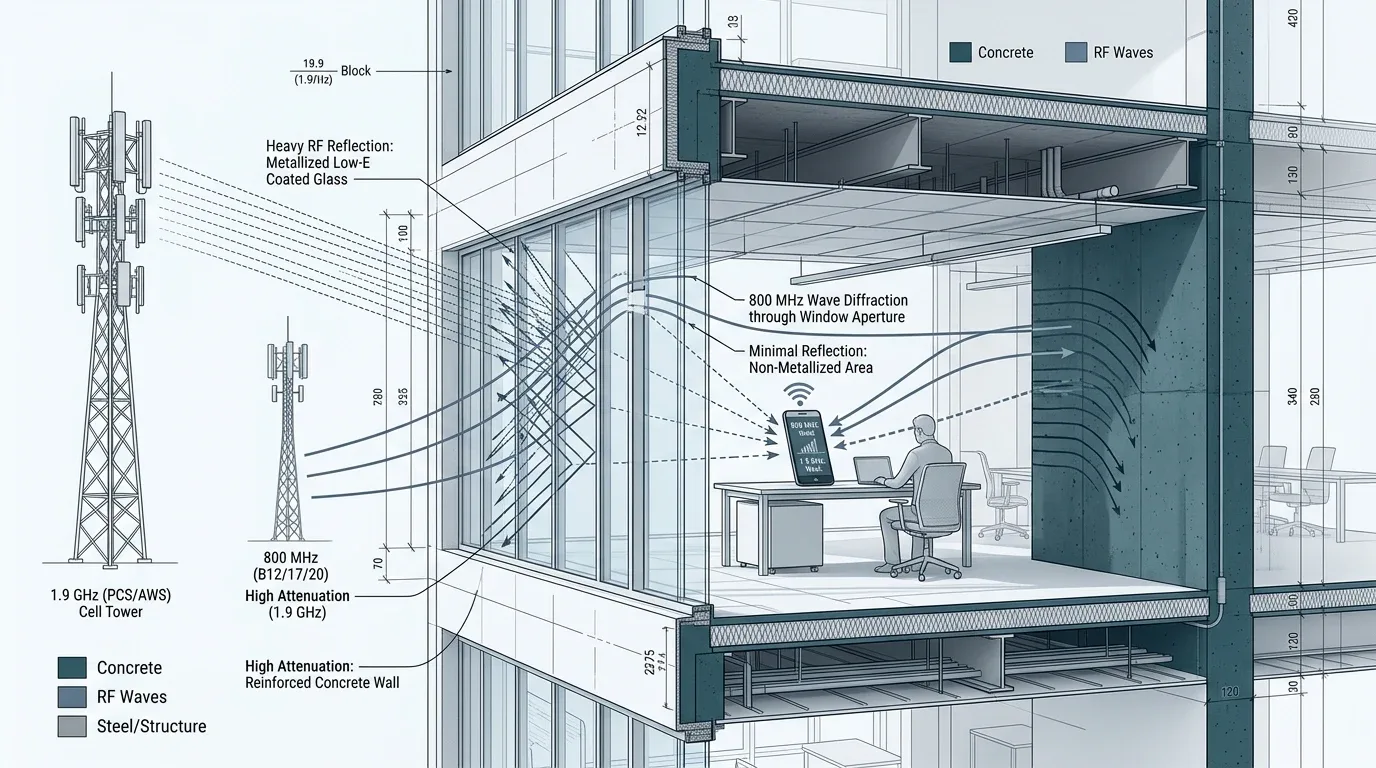
Figure 1: Architectural cross-section of indoor RF attenuation: metallized low-E double-glazed windows and reinforced concrete reflect and absorb 1.9 GHz microwaves (18–25 dB loss), while longer 800 MHz wavefronts diffract through structural apertures to reach indoor handsets.
3. The Arithmetic Reveal: Recovering +24.65 dB of Link Margin
To convert satellite direct-to-cell from a novelty outdoors to a dependable carrier-grade service, SpaceX needed to recover roughly 20 to 25 dB of link margin. It accomplished this not through a single technological breakthrough, but by stacking three distinct physical levers:
A. Friis Frequency Scaling (+7.21 dB Margin Gain)
Because free-space geometric spreading loss is proportional to the square of carrier frequency (f²), migrating from 1950 MHz down to 850 MHz recovers substantial signal energy without altering transmitter power:
ΔFSPL_frequency = 20 · log₁₀(1950 / 850) = 20 · log₁₀(2.2941) = +7.21 dB
Every milliwatt radiated by the phone arrives at the satellite antenna with 5.25× greater power density purely due to electromagnetic wavelength expansion.
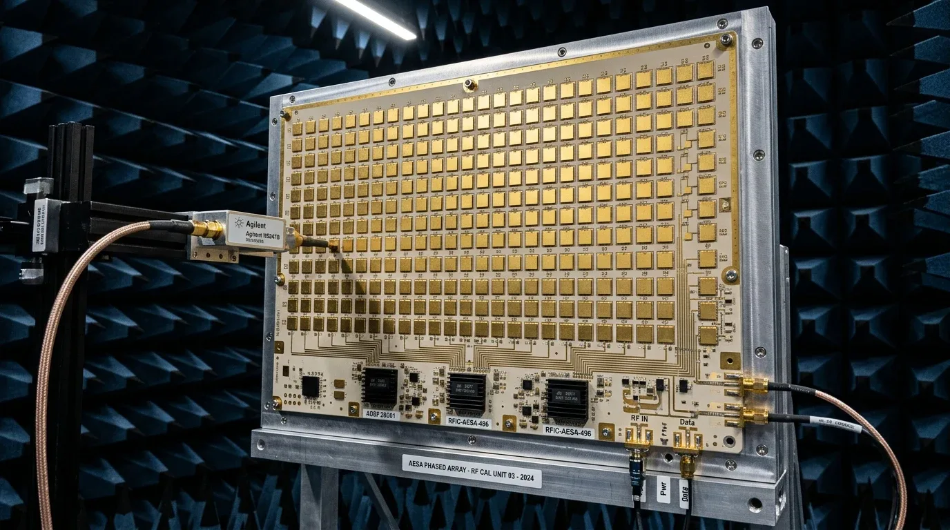
Figure 2: Active Electronically Steered Array (AESA) calibration in an RF anechoic chamber. Hundreds of gold-plated microstrip patch antennas form the high-gain beamforming tile deployed on Starlink Gen2 direct-to-device spacecraft.
B. Wavelength Expansion and Aperture Diffraction (+13.0 dB Margin Gain)
At 1950 MHz, the RF wavelength is λ = 15.4 centimeters. In the 800 MHz band, wavelength expands to λ = 37.5 centimeters. This 2.4× physical expansion transforms wave propagation through buildings:
Knife-Edge Aperture Diffraction: Decimeter waves bend around door frames, structural window mullions, and roof ridges far more efficiently than microwave signals. Instead of requiring direct line-of-sight through concrete slabs, 800 MHz wavefronts diffract through exterior openings and disperse across interior corridors.
Lower Dielectric Dissipation: Electromagnetic skin depth increases at lower frequencies. While 1.9 GHz energy is largely absorbed as thermal dissipation in the exterior skin of masonry and wet concrete, 800 MHz radiation penetrates through walls with 8 to 15 dB lower absorption loss.
C. VLEO Orbital Shell Proximity (+4.44 dB Margin Gain)
The third lever is orbital geometry. Under FCC Authorization DA 26-1078, issued on October 6, 2026, SpaceX was granted permission to operate 15,000 Gen2 Direct-to-Device satellites in nine Very Low Earth Orbit (VLEO) shells between 326 km and 335 km—far below Starlink’s primary 550 km broadband shell:
ΔFSPL_altitude = 20 · log₁₀(550 / 330) = 20 · log₁₀(1.6667) = +4.44 dB
Bringing the orbital receiver 220 km closer to Earth reduces propagation distance by 40%, cutting free-space geometric spreading loss by 64% in both directions.
Summing these three physical mechanisms yields:
- +4.44 dB from VLEO orbital proximity (550 km → 330 km)
- +7.21 dB from Friis low-band frequency scaling (1950 MHz → 850 MHz)
- +13.00 dB from reduced building penetration and material absorption
- Total Net Uplink Link Margin Gain: +24.65 dB
A +24.65 dB net recovery represents a 290-fold increase in effective signal power margin. It shifts the received uplink SNR from a catastrophic -46.5 dB up to -3.5 dB to +2.0 dB—comfortably above the threshold needed for robust QPSK demodulation, PRACH preamble acquisition, and sustained VoLTE voice packets.
4. Architectural Comparison: Mid-Band LEO vs. Low-Band VLEO
The following table contrasts the baseline link parameters of first-generation direct-to-cell systems against SpaceX’s Gen2 800 MHz VLEO architecture:
| Architectural Parameter | Legacy Mid-Band (1.9 GHz / 550 km) | SpaceX Gen2 Low-Band (800 MHz / 330 km) | Net Engineering Delta |
|---|---|---|---|
| Carrier Frequency | 1910–1995 MHz (PCS Band 25) | 814–869 MHz (14 MHz Paired Spectrum) | 2.4× longer wavelength (37.5 cm vs 15.4 cm) |
| Orbital Shell Altitude | 550 km LEO | 326–335 km VLEO (FCC DA 26-1078) | +4.44 dB path loss reduction (40% closer) |
| Nadir Free Space Path Loss | 153.05 dB | 141.40 dB | +11.65 dB total free-space link gain |
| Building Penetration Loss | 18.0 to 25.0 dB (Concrete / Low-E Glass) | 6.0 to 10.0 dB (Aperture Diffraction) | +12.0 to +15.0 dB penetration recovery |
| Handset Transmitter (UE) | +23 dBm (200 mW, 3GPP Class 3) | +23 dBm (200 mW, 3GPP Class 3) | Unchanged; zero hardware modifications needed |
| Indoor Uplink Received SNR | -38.2 dB to -45.5 dB (Undetectable) | -3.5 dB to +2.0 dB (Demodulation PASS) | +24.65 dB net margin turnaround |
| Operational Envelope | Outdoor Line-of-Sight Only (Emergency SOS) | True Indoor Penetration (VoLTE, SMS, 5G Data) | Elevates satellite link into standard carrier utility |
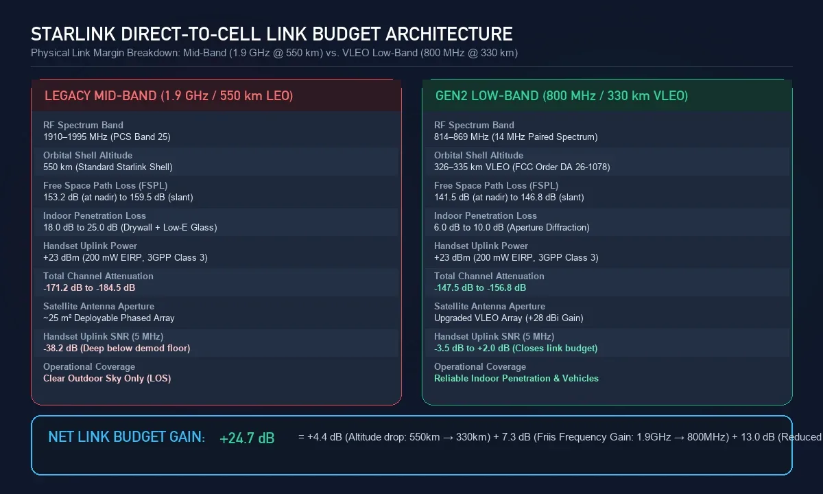
Figure 3: Architectural comparison breakdown illustrating the exact path loss, structural attenuation, and received SNR transition between legacy 1.9 GHz and 800 MHz VLEO direct-to-cell.
5. The Next Constraints: Atmospheric Drag and Laser Mesh Routing
Deploying 15,000 satellites at 326–335 km creates major thermodynamic and orbital challenges. At 330 km, residual thermospheric density is 5× to 8× higher than at 550 km. Under aerodynamic drag equations (F_drag = ½ · ρ · v² · C_d · A), every Gen2 satellite experiences intense continuous deceleration, requiring active propulsion to avert rapid orbital decay.
Orchestrating autonomous station-keeping, dynamic Doppler frequency compensation, and microsecond phased-array handoffs across 15,000 spacecraft traveling at 7.7 km/s requires the same real-time distributed telemetry and high-velocity flight compute pipelines that SpaceX developed for its aerospace and avionics sensor streaming infrastructure.
Furthermore, each VLEO satellite covers a smaller ground footprint than a higher spacecraft, meaning cross-satellite traffic must be handed off across high-throughput optical inter-satellite links (OISLs). Each Gen2 bus carries multiple 400 Gbps space lasers to route packets across a petabit orbital mesh before downlinking to terrestrial internet exchange points.
SpaceX’s decision to own nationwide 800 MHz spectrum outright reflects the same vertical integration strategy demonstrated when SpaceX acquired the AI coding platform Cursor. Rather than remaining permanently dependent on leasing spectrum from terrestrial wireless carriers like T-Mobile, SpaceX is building the foundation to operate as an independent, sovereign mobile network operator.
6. Capacity Limits: What 14 MHz of Paired Spectrum Actually Delivers
While 800 MHz solves the physics of building penetration, engineers must maintain clear expectations regarding aggregate capacity. 14 MHz of paired spectrum corresponds to 7 MHz in the uplink and 7 MHz in the downlink—typically deployed as a standard 5 MHz FDD LTE carrier with 1 MHz guard bands.
In low-SNR satellite channels (-3 dB to +6 dB), modulation is constrained to QPSK or 16-QAM with heavy forward error correction (FEC) rates. At a realistic spectral efficiency of 1.5 to 2.5 bits/second/Hertz, a 5 MHz carrier yields an aggregate capacity of approximately 7.5 Mbps to 12.5 Mbps per beam cell.
Because a satellite spot beam spans roughly 20 to 30 kilometers across the ground, that throughput is shared across all active handsets in the cell. Consequently, Starlink Mobile will not replace home fiber or stream 4K video to dense urban stadium crowds. Instead, it provides an indestructible foundational utility: guaranteed 911 emergency voice dispatch, low-latency messaging, biometric telemetry, and autonomous device command-and-control during natural disasters, power grid failures, and remote field deployments.
Frequently Asked Questions
Why did SpaceX acquire 800 MHz spectrum from Grain Management?
SpaceX acquired up to 14 MHz of paired 800 MHz spectrum to overcome the severe 15–25 dB indoor building penetration loss that cripples higher-frequency 1.9 GHz mid-band signals. The 800 MHz low-band allows standard smartphones to maintain satellite connections indoors without specialized hardware.
What did the FCC authorize in Order DA 26-1078?
On October 6, 2026, the FCC issued Order DA 26-1078 authorizing SpaceX to construct, deploy, and operate 15,000 dedicated Direct-to-Device (D2D) Gen2 satellites in Very Low Earth Orbit (VLEO) between 326 km and 335 km across nine orbital shells, requiring 7,500 operational satellites by 2032 and all 15,000 by 2035.
Will standard smartphones work with Starlink 800 MHz direct-to-cell?
Yes. Because 800 MHz (3GPP Band 26 / SMR) is already integrated into the baseband modems and RF front-ends of almost all modern LTE and 5G smartphones, users will not need to purchase specialized satellite phones, external dongles, or custom antennas.
How does Very Low Earth Orbit (330 km) improve the link budget?
Operating at 326–335 km VLEO brings the satellites 220 km closer to Earth than standard 550 km orbits. By the Friis transmission formula, this 40% reduction in distance reduces Free Space Path Loss by ~4.44 dB, cutting signal attenuation by nearly 65% in both directions.