
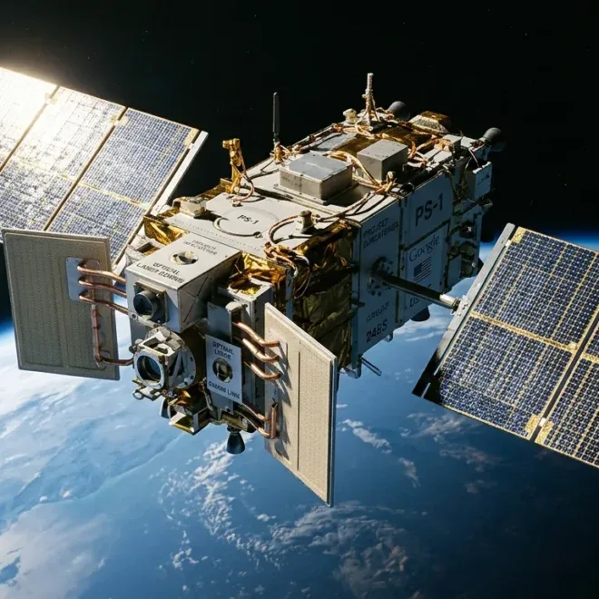

Google’s Project Suncatcher proposes deploying clusters of Tensor Processing Units (TPUs) into low Earth orbit (LEO) to tap into continuous solar energy and bypass terrestrial power grid bottlenecks. Ground tests at UC Davis Crocker Nuclear Laboratory demonstrate that 6th-generation Trillium TPU logic withstands cumulative total ionizing doses exceeding five-year LEO mission profiles. However, High Bandwidth Memory (HBM) degradation, vacuum thermal radiation limits requiring roughly 3.2 m² of radiator area per kilowatt, and optical beam tracking across close-proximity satellite formations present severe physical bottlenecks.
For the past decade, hyperscalers expanded machine learning clusters by scaling terrestrial concrete, copper, and cooling water. But as frontier training runs demand gigawatt-class campuses and regional utility interconnection queues stretch past 2032—forcing unprecedented private energy moves like Microsoft’s 835 MW nuclear restart at Three Mile Island and 20 GW multi-campus infrastructure bets—terrestrial constraints are shifting from algorithmic efficiency to raw thermodynamics and civil infrastructure.
Project Suncatcher, led by Travis Beals and Google’s Paradigms of Intelligence research team in partnership with Planet Labs, is the industry’s first concrete attempt to bypass the terrestrial power wall entirely. Rather than competing for municipal power grids, river water rights, and substations, Suncatcher evaluates launching modular, solar-powered satellite swarms carrying custom silicon directly into Sun-synchronous dawn-dusk orbits.
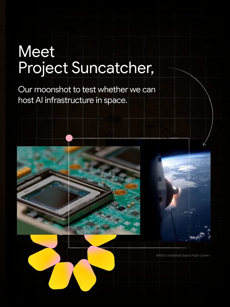
Below is the definitive technical audit of Google’s orbital compute blueprint: the thermodynamics of Stefan-Boltzmann heat rejection in a vacuum, the proton-beam radiation resilience of Trillium ASICs versus 3D-stacked HBM, the link budgets of 10 Tbps free-space optical Dense Wavelength Division Multiplexing (DWDM), and the empirical economics governing Wright’s Law launch costs.
Terrestrial Limits vs. Orbital Realities: The Physical Trade-Off Matrix
The architectural justification for Project Suncatcher rests on a single thermodynamic divergence: terrestrial solar infrastructure suffers from atmospheric attenuation, diurnal dark periods, weather intermittency, and land footprints, whereas orbital solar panels operate in an uninterrupted radiant stream.
In a Sun-synchronous dawn-dusk low Earth orbit (typically 500 km to 800 km altitude), a satellite orbits along the day-night terminator line. Because the orbital plane precesses at the exact rate of Earth’s revolution around the Sun, the spacecraft avoids the planet’s shadow cone for over 99% of its operational life, bathed in continuous, unattenuated solar radiation.
The Insolation Multiplier: At Air Mass Zero (AM0), space solar irradiance is a constant S0 ≈ 1,361 W/m². On Earth, atmospheric absorption, Rayleigh scattering, cloud opacity, and diurnal day-night cycles reduce average continental insolation to 160–220 W/m². In a dawn-dusk Sun-synchronous orbit, solar arrays generate up to 8.4 times more cumulative kilowatt-hours per day per kilogram of cell than ground-based arrays, eliminating the massive multi-megawatt battery storage buffers mandatory for terrestrial microgrids.
However, trading municipal power grids for orbital space swaps civil grid interconnection friction for hostile physics. The table below audits the operational constraints separating a terrestrial TPU v5p/Trillium pod from Google’s planned Suncatcher satellite architecture:
| Subsystem Architecture | Terrestrial TPU Pod (v5p / Trillium) | Orbital Suncatcher Swarm Node |
|---|---|---|
| Primary Power Source | High-voltage regional utility grid (substation drops: 115 kV–500 kV), backup diesel generators | Direct AM0 photovoltaic solar arrays (Gallium Arsenide triple-junction or perovskite tandem) |
| Duty Cycle & Intermittency | 99.999% grid uptime; localized curtailment risks during regional heatwaves | >99% continuous insolation in dawn-dusk SSO (600 km); brief seasonal eclipse penumbras (<15 min) |
| Heat Rejection Physics | Convective liquid-to-air cooling; direct-to-chip chilled liquid cold plates, evaporative cooling towers | Pure radiative cooling (Stefan-Boltzmann T4); loop heat pipes (LHP) to dual-sided deployed radiator wings |
| Interconnect Medium | Single-mode optical fibers (SMF-28), MEMS-based Optical Circuit Switches (OCS), 3D Torus topology | Free-Space Optical (FSO) links; multi-aperture DWDM spatial multiplexing (10 Tbps inter-satellite links) |
| Propagation Latency | Silica core index n ≈ 1.468 ⇒ light propagation speed ≈ 204,200 km/s (4.9 μs/km) | Vacuum propagation c ≈ 299,792 km/s (3.33 μs/km); 31.8% lower physical flight latency per unit distance |
| Radiation Environment | Sea-level background; atmospheric and magnetospheric shielding (<0.003 rad/year) | Trapped protons (South Atlantic Anomaly), Galactic Cosmic Rays (GCRs), solar particle events (>1–5 krad/year) |
| Capital Lifecycle & Upgrades | Building shell: 25–30 years; server blade refresh cycle: 3–5 years; continuous physical hot-swapping | Satellite design life: 5 years; zero physical maintenance; de-orbit disposal via atmospheric burn-up |
Thermal Vacuum Mechanics: Why Space Is a Thermal Insulator, Not a Refrigerator
Popular commentary on space data centers frequently falls into a primary physics trap: assuming that because the deep cosmos has a cosmic microwave background temperature of 2.7 Kelvin (−270.45°C), cooling high-density AI accelerators in space must be effortless.
In orbital mechanics and spacecraft engineering, the exact opposite is true: the vacuum of space is one of the most effective thermal insulators known to physics.
On Earth, a 600-watt TPU blade transfers thermal energy away from its package via high-velocity fluid convection: liquid coolant flows through copper cold plates micro-machined with internal fins, carrying heat to heat exchangers and cooling towers where millions of cubic meters of ambient air conduct and convect that heat into the planetary atmosphere.
In low Earth orbit, ambient gas density is between 10−9 and 10−12 atmospheres. There are no fluid molecules to carry away heat via convection or conduction. The only mechanism for dissipating heat from a silicon die into space is thermal electromagnetic radiation, strictly governed by the Stefan-Boltzmann law.
The Radiative Surface Penalty: Where σ = 5.67037 × 10⁻⁸ W/(m²·K4), ε ≈ 0.90 (high-emissivity optical solar reflector coating), and Tsink is the effective orbital thermal environment. Because a satellite in LEO views Earth’s infrared glow (237 W/m²) and reflected solar albedo, Tsink is approximately 250 Kelvin (−23°C)—not deep space. If a TPU radiator operates at a safe ceiling of 65°C (338 K), the net flux is barely 315 W/m².
Sizing the Radiator Mass for a Trillium Satellite
Let us calculate the physical radiator size required to cool a single Suncatcher satellite node hosting four Trillium TPUs:
- Thermal Dissipation Budget:
- 4 × Trillium TPUs at sustained matrix multiplication: 4 × 650 W = 2,600 W.
- Accompanying switch ASICs, power conditioning units (PDU), transceiver optics, and battery charge controllers: ≈ 600 W.
- Total continuous thermal rejection load: 3,200 W (3.2 kW).
- Silicon Thermal Limits:
- Commercial accelerator silicon experiences accelerated electro-migration and gate-oxide breakdown if junction temperatures exceed Tjunction > 95°C (368 K).
- In spacecraft design, thermal resistance across heat pipes, evaporator interfaces, and fluid loops imposes a ΔT of at least 25°C to 30°C between the silicon die and the outer radiating fin surface.
- Consequently, the maximum radiator operating temperature cannot exceed Trad = 65°C (338.15 K).
- Net Radiative Flux:
- Radiator emission: qemit = 0.90 × (5.67037 × 10−8) × (338.15)4 ≈ 666.8 W/m².
- Environmental absorption (edge-on orientation to Sun, viewing cold space and oblique Earth limb): qabsorbed ≈ 350 W/m².
- Net Radiative Capacity: qnet ≈ 316.8 W/m².
- Required Radiator Area:
- Required area: A = 3,200 W / 316.8 W/m² ≈ 10.1 m².
- Even assuming a deployed, double-sided radiator panel that radiates from both faces, the spacecraft requires 5.05 m² of physical panel aperture dedicated exclusively to dumping heat.
To transfer 3.2 kW of thermal energy across a 5-meter deployed wing without a gravitational vector, the spacecraft cannot use conventional pump impellers, which introduce mechanical vibration, bearing wear, and single-point seal failures. Suncatcher relies on Loop Heat Pipes (LHPs) and Oscillating Heat Pipes (OHPs).
LHPs use sub-micron sintered metal wicks (typically nickel or titanium) to generate high capillary pressure, evaporating high-purity ammonia at the TPU cold plate and driving the vapor phase along smooth-bore flexible transport lines out to the deployed radiator panels, where it condenses and wicks back. The entire system is passive, contains no moving parts, and survives launch acoustic loads up to 142 dB OASPL.
Silicon Under Ionizing Flux: Trillium ASICs vs. 3D-Stacked High Bandwidth Memory
In terrestrial data centers, soft error rates (SER) in compute silicon are primarily driven by trace alpha-particle emissions from packaging mold compounds and atmospheric secondary neutrons generated by cosmic ray spallation in the upper atmosphere. Hyperscalers design terrestrial hardware around an expected Failure in Time (FIT) rate on the order of 10−9 errors per device hour.
In low Earth orbit, that protective atmospheric cushion disappears entirely. The spacecraft traverses a continuous ionizing radiation field composed of:
- Trapped Protons and Electrons: Concentrated in the Van Allen radiation belts and descending to low altitudes over the South Atlantic Anomaly (SAA), where the geomagnetic field dips closest to Earth.
- Galactic Cosmic Rays (GCRs): High-energy, highly ionized atomic nuclei (HZE ions, from protons up to iron) originating outside the solar system, carrying energies from 100 MeV to tens of GeV.
- Solar Particle Events (SPEs): Sporadic coronal mass ejections that flood orbital paths with relativistic proton fluxes exceeding 105 protons/(cm²·s).
Google Suncatcher Proton Beam Exposure Protocol (Trillium ASIC & HBM)
Empirical Finding: As documented in Google Research’s system paper (arXiv:2511.19468), Trillium compute logic (Matrix Multiply Units, Vector Units, and control sequencers) demonstrated zero hard destructive latch-ups up to and beyond the 5-year mission cumulative dose. However, 3D-stacked High Bandwidth Memory (HBM) emerged as the single point of failure, exhibiting uncorrectable Multi-Bit Upsets (MBUs) at fluences an order of magnitude lower than the main logic die.
Why HBM Collapses Before Matrix Processing Units
The vulnerability of modern AI accelerators in orbit is not the digital logic: it is the density and manufacturing geometry of the memory stack.
Google’s Trillium (TPU v6e) integrates massive Matrix Multiply Units (MXUs) fabricated on advanced FinFET nodes. Much like contemporary enterprise hyperscale infrastructure deploying custom ASIC accelerator clusters at scale, modern FinFET channel geometries limit the sensitive cross-sectional volume susceptible to charge deposition in standard CMOS logic cells. When an energetic proton strikes an MXU logic transistor, it generates an electron-hole pair plasma. Unless this charge exceeds the critical switching charge (Qcrit) during an active clock latch edge, the transient charge simply disperses into the substrate without corrupting system state (Single Event Transient, or SET).
In contrast, High Bandwidth Memory (HBM) represents an extreme vulnerability surface for three structural reasons:
- Microscopic Storage Capacitance: HBM DRAM dies rely on deep-trench or stacked cylindrical capacitors holding mere femtofarads (10−15 Farads) of charge (<20,000 electrons per bit). A single secondary proton recoil or heavy ion track deposits enough charge along its ionization path (Linear Energy Transfer, LET) to flip multiple neighboring storage cells simultaneously.
- Dense Through-Silicon Via (TSV) Arrays: HBM stacks 4, 8, or 12 active DRAM dies vertically on top of an active base logic die using tens of thousands of micro-bumps and TSVs. Ionizing radiation passing through the vertical interposer can disrupt the high-speed serialized Command/Address (C/A) bus, corrupting read/write pointers across an entire memory channel rather than an isolated byte.
- Failure of Standard SECDED ECC: Standard single-error correction, double-error detection (SECDED) handles isolated, stochastic Single Event Upsets (SEUs). In space, a single energetic ion entering at an oblique angle penetrates multiple adjacent memory cells within the same word line, triggering a Multi-Cell Upset (MCU). Standard SECDED cannot correct two simultaneous bit errors in the same 64-bit word; it flags an uncorrectable ECC error and halts the entire processing node.
| Silicon Component | Radiation Sensitivity Mechanism | Failure Mode in Orbit | Suncatcher Engineering Mitigation |
|---|---|---|---|
| MXU / Vector Compute Logic | Total Ionizing Dose (TID) gate dielectric wear; single event logic transients (SET) | Isolated mathematical calculation glitch in matrix accumulation; transient gradient distortion | FinFET structural resilience; algorithmic loss-gradient bounds; redundant forward-pass parity checks |
| 3D HBM DRAM Cells | Low critical charge (Qcrit < 3 fC); charge collection across adjacent capacitor nodes | Multi-Cell Upsets (MCUs); catastrophic weight tensor corruption; silent data corruption (SDC) | Aggressive background memory scrubbing (10× terrestrial rate); Reed-Solomon symbol-level ECC |
| Interposer TSV / PHY Layer | High-speed differential trace crosstalk induced by charge deposition in substrate | Link synchronization loss on memory bus; forced retraining sequence; memory channel timeout | Sub-millimeter localized tantalum/tungsten shielding directly above the memory interposer |
| Power Distribution / VRMs | Single Event Burnout (SEB) & Single Event Gate Rupture (SEGR) in high-voltage MOSFETs | Permanent destructive short-circuit; total loss of power rail to accelerator ASIC | Radiation-hardened GaN (Gallium Nitride) switches; voltage derating to ≤60% of breakdown rating |
To address this, Google’s system architecture decouples the training loop from strict hardware infallibility. In terrestrial clusters, a single uncorrectable ECC error crashes the entire synchronous distributed training job, forcing a rollback to the last saved checkpoint on Google Cloud Storage.
In Suncatcher’s orbital software stack, the optimizer is designed for lossy hardware:
- Stochastic Weight Checkpointing: High-frequency, asynchronous model state snapshots stored in localized SRAM rather than HBM.
- Loss Gradient Sanitization: If an energetic proton flips a sign bit in an unmasked weight tensor, producing a localized NaN (Not-a-Number) or gradient explosion (‖∇L‖ > τ), an automated hardware hook drops the tainted micro-batch without aborting the cluster job.
- Tantalum Spot Shielding: Rather than cladding the entire satellite in heavy lead or aluminum (which increases launch mass penalties and emits secondary Bremsstrahlung radiation), Google applies precision 2 mm tantalum spot shields directly over the HBM micro-bump stacks.
The Network Barrier: Free-Space Optical DWDM & Close-Formation Swarms
Distributed AI training is not a compute-bound problem: it is a bisection bandwidth and latency problem.
Much like the interconnect trade-offs analyzed in elastic chip-to-chip distributed compute fabrics, training frontier neural networks via Megatron-style 3D parallelism (Tensor Parallelism, Pipeline Parallelism, and Data Parallelism) requires worker nodes to continuously exchange intermediate activation tensors and weight gradients. Tensor Parallelism requires all-to-all communication primitives (AllReduce, AllGather) executed across every single transformer layer.
On Earth, Google solves this with custom optical hardware: the TPU Optical Circuit Switch (OCS), which dynamically routes fiber-optic signals between TPU pods via 2D MEMS mirrors, delivering up to 4.8 Tbps of bisection bandwidth per node with sub-microsecond optical propagation delays.
Replicating terabit-scale bisection bandwidth in the vacuum of space presents immense geometric and physical challenges.
The Proximity Invariant: Geometric path loss scales quadratically with distance (d2). Traditional Inter-Satellite Optical Links (such as Starlink or SDA Tranche satellites) operate over separation distances of 1,000 km to 4,000 km, requiring heavy optical telescopes, narrow micro-radian pointing mechanisms, and low bitrates (10–100 Gbps). By compressing the satellite cluster into an ultra-dense formation flight baseline (d ≤ 100 meters to 1 kilometer), path loss drops by 60 to 80 dB, enabling Google to utilize unmodified, low-power Commercial Off-The-Shelf (COTS) DWDM transceivers.
Dense Formation Flight: The 81-Satellite Cluster
Google’s architectural breakthrough in the Suncatcher design paper (arXiv:2511.19468) is the realization that megawatt AI compute cannot be deployed as a constellation of distant satellites; it must fly as a tightly coupled, co-orbiting swarm.
4× 2-Axis Optical Gimbal Terminals
COTS C-band DWDM Transceiver Array
Bandwidth: 10 Tbps Bidirectional
Wavelength: 1550 nm (32–64 Channels)
Bisection Capacity: Petabit-Scale Swarm
Vacuum Flight: 3.336 μs/km (−31.8% Latency)
This close baseline unlocks three critical capabilities:
- COTS DWDM Optical Transceivers: Because the link distance is under 1,000 meters, optical beam divergence is minimal. The received optical power is high enough to drive standard 100 GHz C-band Dense Wavelength Division Multiplexing (DWDM) optical engines identical to those used inside terrestrial data centers. By multiplexing 32 to 64 laser wavelengths across the 1550 nm optical window, each optical terminal achieves aggregate bidirectional throughput of 10 Terabits per second (10 Tbps) per inter-satellite link.
- Spatial Multiplexing via Aperture Arrays: At kilometer baselines, the beam diameter at the receiving satellite is mere centimeters. Suncatcher nodes can deploy multiple optical apertures (e.g., a 2×2 or 4×4 spatial array) on each face of the spacecraft without cross-channel optical interference, scaling inter-node bandwidth into the tens of terabits.
- The Vacuum Velocity Advantage: In terrestrial single-mode glass fiber (Corning SMF-28), the speed of light is slowed by the glass core’s refractive index (n ≈ 1.4682 at 1550 nm):
In orbit, the laser beam propagates through vacuum (n = 1.0000):
Free-space optical links transmit intermediate activations 31.8% faster than the best terrestrial fiber optic cables. Over an 81-satellite cluster, inter-node round-trip time (RTT) for collective communication primitives is strictly dominated by transceiver serialization latency rather than physical time-of-flight.
- Microradian Pointing Jitter (“Coin-Size Target from Miles Away”): In its official engineering briefing, Google illustrated the acquisition challenge with an intuitive physical benchmark: maintaining multi-terabit laser links between dynamic satellites is “similar to hitting a coin-size target from miles away while both points are in motion.” Quantitatively, a 25 mm coin at a distance of 2.5 kilometers subtends an angular diameter of barely 10.05 microradians (0.00057°). In low Earth orbit, satellite attitude jitter—induced by reaction wheel micro-vibrations, solar array thermal snapping across orbital terminators, and attitude control thruster pulses—regularly exceeds 20 to 50 microradians. To prevent link dropouts, Suncatcher optical terminals integrate high-bandwidth Fast Steering Mirrors (FSMs) driven by piezo-electric actuators operating at kilohertz bandwidths, maintaining closed-loop sub-microradian optical tracking.
The Orbital Mechanics Penalty: Relative Drift & HCW Control
While close proximity solves the optical link budget, it introduces severe orbital mechanics risks.
Two satellites placed in low Earth orbit do not simply hover next to one another. Due to Earth’s non-spherical gravitational harmonics (specifically the J2 zonal harmonic coefficient, representing Earth’s equatorial bulge) and differential atmospheric drag, any minute variation in orbital altitude or inclination causes satellites to drift apart or cross paths catastrophically.
To prevent collisions while maintaining optical pointing accuracy within microradians, each Suncatcher node must continuously solve the Hill-Clohessy-Wiltshire (HCW) equations of relative motion:
The Station-Keeping Tax: Where ω is the orbital angular velocity, x is the radial axis, y is the along-track velocity vector, and z is the cross-track orbital normal. Because cross-track oscillations decouple from radial-along-track motion, maintaining an 81-node passive relative ellipse requires continuous, ultra-fine thrust impulses (fx, fy, fz). Suncatcher satellites must carry high-specific-impulse electric propulsion (Hall-effect or electrospray thrusters) firing continuous micro-newton bursts to compensate for differential drag.
If a single thruster valve sticks or an attitude control reaction wheel suffers single-event latch-up, that satellite drifts across the cluster trajectory, threatening an orbital cascade collision (Kessler Syndrome) that could obliterate the multi-million-dollar computing asset within seconds.
Unit Economics: Starship Heavy-Lift Parity & Wright’s Law
The viability of Project Suncatcher does not ultimately hinge on radiation testing or laser pointing: it is dictated by the cost per kilogram of launch mass.
On Earth, hyperscalers build megawatt-class data centers at a capital expenditure (CAPEX) of $8 million to $12 million per Megawatt of IT capacity (excluding accelerator silicon), with retail power purchase agreements (PPAs) ranging between $0.045 and $0.090 per kilowatt-hour.
In space, solar fuel is free, and real estate taxes are zero. But launch costs represent an upfront capital barrier that must be amortized over the satellite’s operating lifetime.
The Parity Crossover: Where C(V) is the marginal launch cost as cumulative launch volume V doubles, with learning parameter b ≈ 0.20–0.25. At historical Falcon 9 launch prices ($1,800–$2,500/kg), orbital AI compute is economically absurd—launching a single 1 MW cluster adds $150M+ in pure freight overhead. However, if full-scale, fully reusable heavy-lift vehicles (e.g., SpaceX Starship) drive marginal launch costs down to $150–$200/kg by the mid-2030s, the amortized 5-year Total Cost of Ownership (TCO) of orbital compute crosses below terrestrial gigawatt buildouts.
Total Cost of Ownership (TCO) Breakdown: 1 MW Orbital Pod vs. Terrestrial Facility
The following economic audit models a 1 Megawatt (IT load) cluster operating over a 5-year lifecycle. The orbital cluster assumes 250 satellite nodes (4 kW each), totaling approximately 80,000 kg of deployed dry mass:
| Cost Architecture Category | Terrestrial 1 MW Facility (5-Year TCO) | Project Suncatcher 1 MW Swarm (@ $200/kg) |
|---|---|---|
| Substation & Interconnection Queue | $2.5M – $4.0M (including utility upgrades and 4-year legal/permitting costs) | $0 (zero terrestrial grid or substation interconnection) |
| Power Consumption OPEX | $3.15M (at $0.06/kWh, 1.2 PUE, 8,760 hours/year × 5 years) | $0 (continuous orbital solar generation) |
| Cooling Water & Chiller Infrastructure | $1.2M (mechanical chillers, cooling towers, treatment chemical consumables) | $1.8M (loop heat pipes and deployed radiator wing fabrication) |
| Launch Freight / Transport | $0.15M (ground freight, server rack transport) | $16.0M (80,000 kg dry mass launched to LEO @ $200/kg) |
| Satellite Bus & Solar Array Hardware | $0 (standard 19-inch steel server racks) | $12.5M (250 satellite buses, reaction wheels, star trackers, solar arrays) |
| Total 5-Year Infrastructure TCO | $7.0M – $8.5M (excl. silicon) | $30.3M (excl. silicon) |
The table exposes the core economic reality: even at an aggressive $200/kg launch cost, orbital compute is approximately 3.8 times more expensive than terrestrial data center infrastructure over a 5-year horizon.
For Project Suncatcher to achieve economic superiority, one of two scenarios must materialize:
- Launch costs drop to sub-$50/kg: Starship achieves aircraft-like turnaround economics, reducing launch freight for an 80-ton cluster to under $4M.
- Terrestrial interconnect grid lockouts become absolute: If regional utilities refuse to connect new AI loads above 50 MW without 10-year delays and $150/MWh penalty tariffs, the value of time-to-compute dominates raw CAPEX. As next-generation foundation models like Google’s Gemini 4 enter massive post-training regimes, an AI lab that deploys a 100 MW orbital cluster in 18 months beats a terrestrial rival waiting until 2035 for utility substations.
Roadmap: Planet Labs Prototype to the 2027 Dual-Satellite Link
Google is not jumping directly to an 81-satellite swarm. The project follows a phased orbital testbed progression:
Radiation: 67.5 MeV Proton Beam
Finding: Logic survived >30 krad TID.
Bus: Planet Labs Pelican
Loads: 10g vehicle / 50–100g shock.
Baseline: 500 m – 2 km Separation
Goal: 10 Tbps DWDM tensor link.
The 2026 MVP Prototype Launch: 100g Mechanical Shock & TVAC Qualification
The first physical test of Project Suncatcher is scheduled for launch aboard a SpaceX Transporter-18 rideshare mission.
Developed in direct engineering collaboration with Planet Labs, the MVP satellite integrates a functional Google TPU payload directly into a modified Planet Earth-observation satellite bus.
As Google disclosed in its official technical briefing, a rocket ascent to low Earth orbit lasts approximately 10 minutes, subjecting the spacecraft structure to sustained acceleration forces up to 10 times the force of gravity (10 g). Crucially, due to acoustic resonance coupling inside the payload fairing, individual internal components—specifically the TPU silicon die, FinFET micro-bumps, and high-density ball grid arrays (BGA)—experience severe dynamic amplification forces reaching 50 to 100 g.
To qualify the payload for flight, Google engineers subjected the integrated satellite to intense 3-axis shaker table vibration testing, confirming that silicon wire bonds, underfill adhesives, and solder matrices held without mechanical failure.
Furthermore, because convective airflow is absent in orbit, Google validated the thermal loop in ground Thermal Vacuum (TVAC) chambers, reproducing the orbital thermal-vacuum cycle with prototype loop heat pipes and deployed radiator wings prior to shipment to the launchpad.
The primary operational objectives of the MVP orbital mission include:
- Ascent Load and Micro-Crack Telemetry: Verifying whether 50–100g launch shocks induced micro-fractures in the Trillium FinFET channels or thermal interface material (TIM) delamination under operational heat loads.
- Microgravity Two-Phase Fluid Circulation: Measuring the capillary pumping pressure and evaporator thermal resistance of the loop heat pipes in true zero-g across rapid sunlit-to-penumbra thermal transients.
- Live SAA Radiation Telemetry: Capturing live Single Event Upset (SEU) and Multi-Cell Upset (MCU) rates across HBM and SRAM arrays as the spacecraft passes through the South Atlantic Anomaly, correlating in-orbit bit-flips against UC Davis proton beam ground benchmarks.
The 2027 Dual-Satellite Mission: Closing the Optical Link
Following the telemetry from the MVP mission, Google and Planet Labs plan a two-satellite mission by early 2027.
This mission represents the true technological hurdle for Suncatcher: flying two spacecraft in coordinated formation at a baseline separation between 500 meters and 2 kilometers, acquiring and locking free-space optical laser terminals, and executing a distributed tensor multiplication across an inter-satellite link.
If the dual-satellite link achieves sustained 10 Tbps DWDM transmission with bit error rates (BER) below 10−9 without losing pointing lock during thruster firings, Project Suncatcher will prove that the physical fabric of distributed AI compute can survive outside Earth’s biosphere.
Architectural Verdict: Moonshot Viability & Technical Verdict
Google’s Project Suncatcher is not vaporware, but it is not an imminent replacement for terrestrial hyperscale infrastructure. It is a rigorously engineered contingency architecture designed for a world where terrestrial power grids fail to keep pace with algorithmic demand.
Our forensic technical verdict across the four core disciplines yields clear milestones:
- Silicon Logic Resilience (PASS): Google’s 6th-generation Trillium TPUs possess sufficient intrinsic radiation tolerance to survive five-year low Earth orbit lifetimes without destructive latch-up.
- Memory Subsystem Integrity (CRITICAL BOTTLENECK): Standard 3D High Bandwidth Memory (HBM) is poorly suited for the orbital radiation environment. Without aggressive tantalum spot shielding, hardware-level symbol ECC, and fault-tolerant gradient checkpointing, orbital TPUs will suffer debilitating Silent Data Corruption.
- Vacuum Thermal Rejection (HIGH FRICTION): Radiative cooling imposes a severe physical mass and surface penalty. Dissipating even modest multi-kilowatt compute loads requires 5 to 10 square meters of deployed radiator panels per node, increasing satellite drag, attitude inertia, and launch payload volume.
- Free-Space Optical DWDM (FEASIBLE): Close-formation flight (sub-kilometer baselines) successfully circumvents space link budget penalties, allowing COTS DWDM components to achieve 10 Tbps bisection bandwidth with lower physical propagation latency than terrestrial glass fiber.
- Launch Economics (FUTURE-CONDITIONAL): Suncatcher remains economically non-viable at current launch prices ($1,800/kg). The entire economic thesis depends on heavy-lift launch vehicles achieving routine, reusable flight costs below $200/kg by the 2030s.
Until fully reusable rockets make freight to orbit cheaper than concrete substations on Earth, Google’s TPUs will remain firmly anchored to planetary bedrock. But when the terrestrial power wall becomes insurmountable, the engineering foundation laid by Suncatcher ensures that hyperscalers will not stop scaling—they will simply look up.